-40%
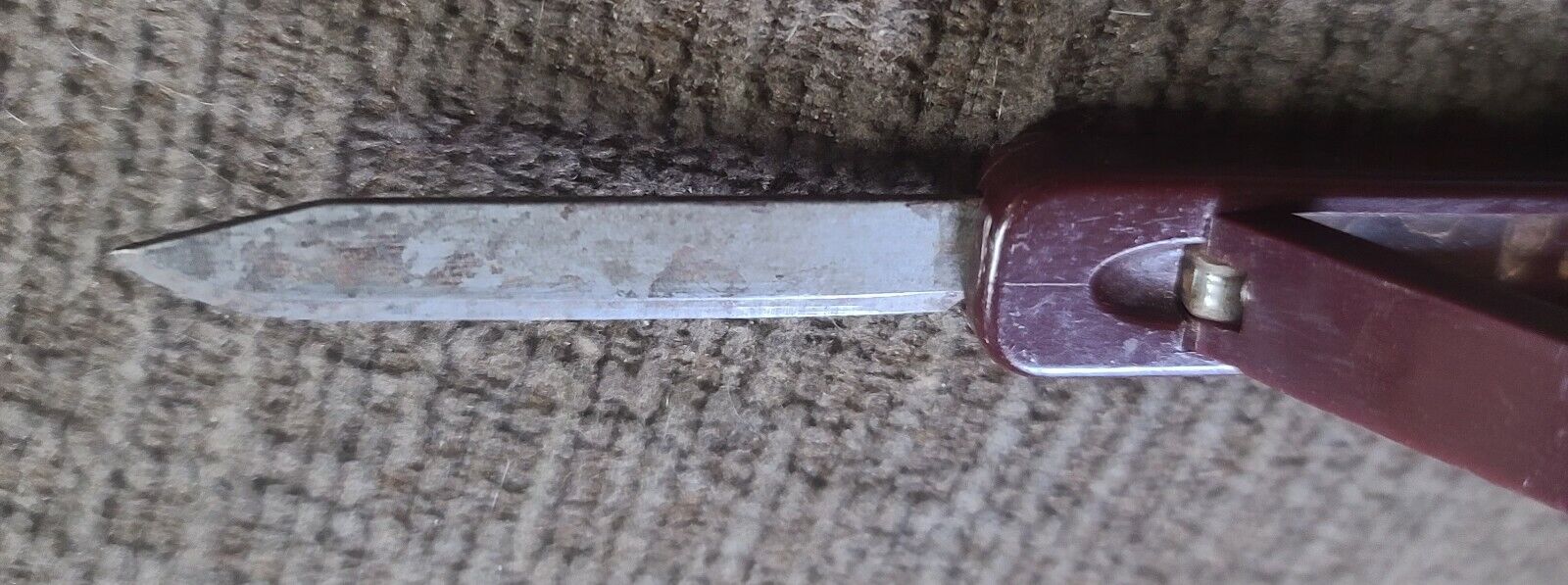
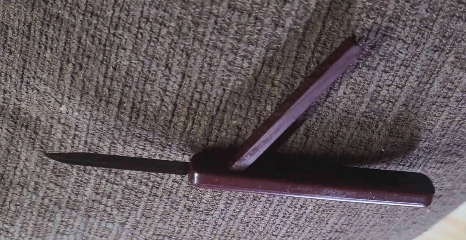
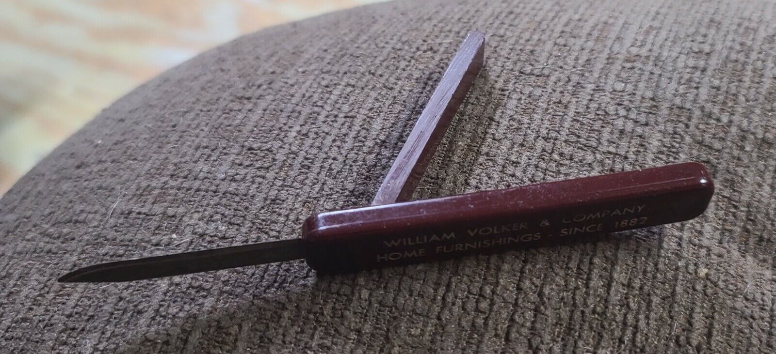
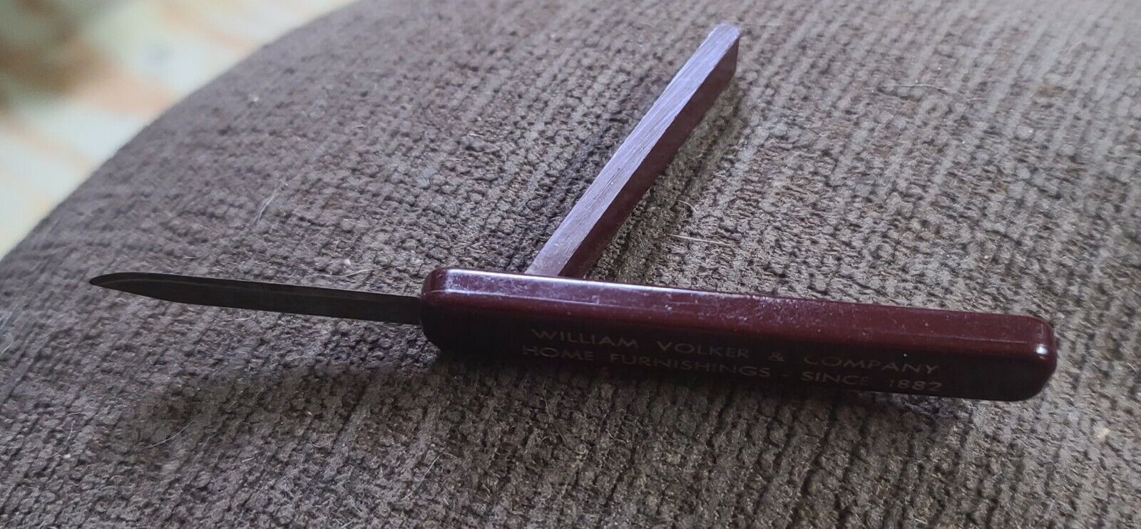
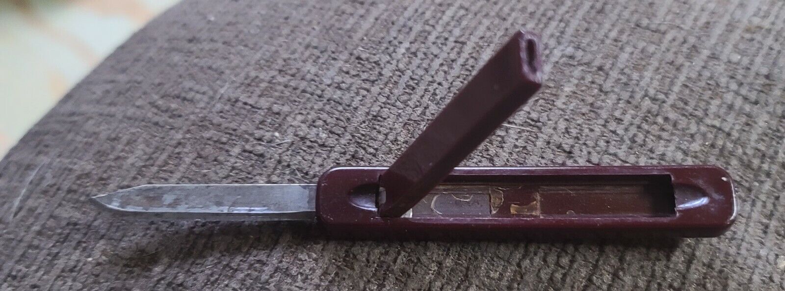
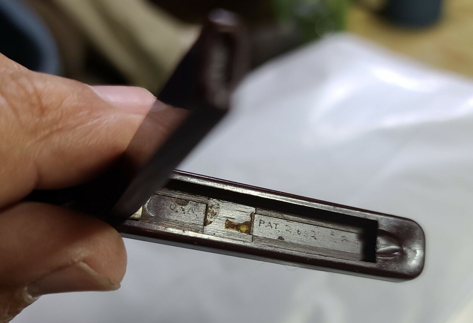
P. A . Unsinger Sliding blade, Bake light?, 1949, knife construction, USA
$ 4.21
- Description
- Size Guide
Description
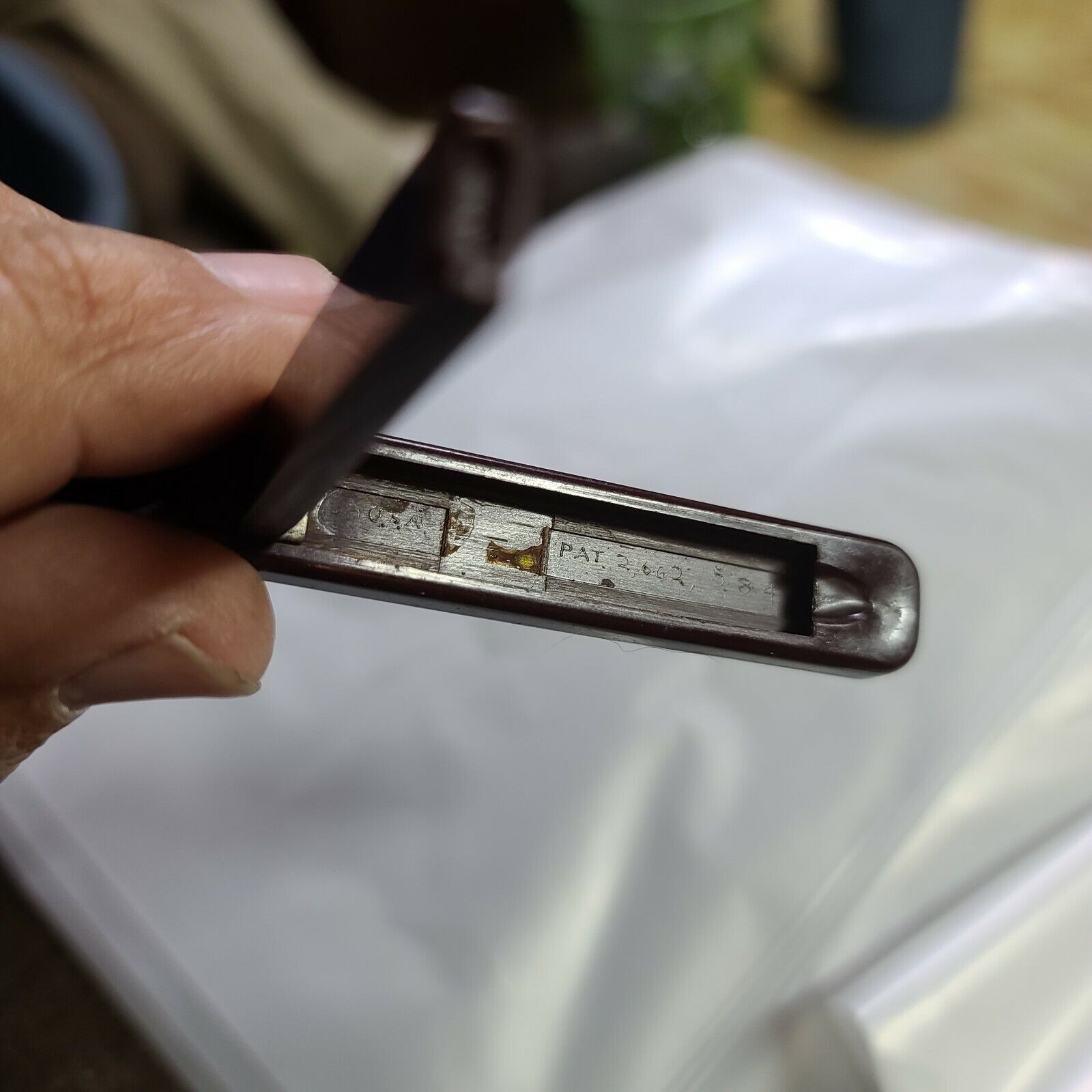
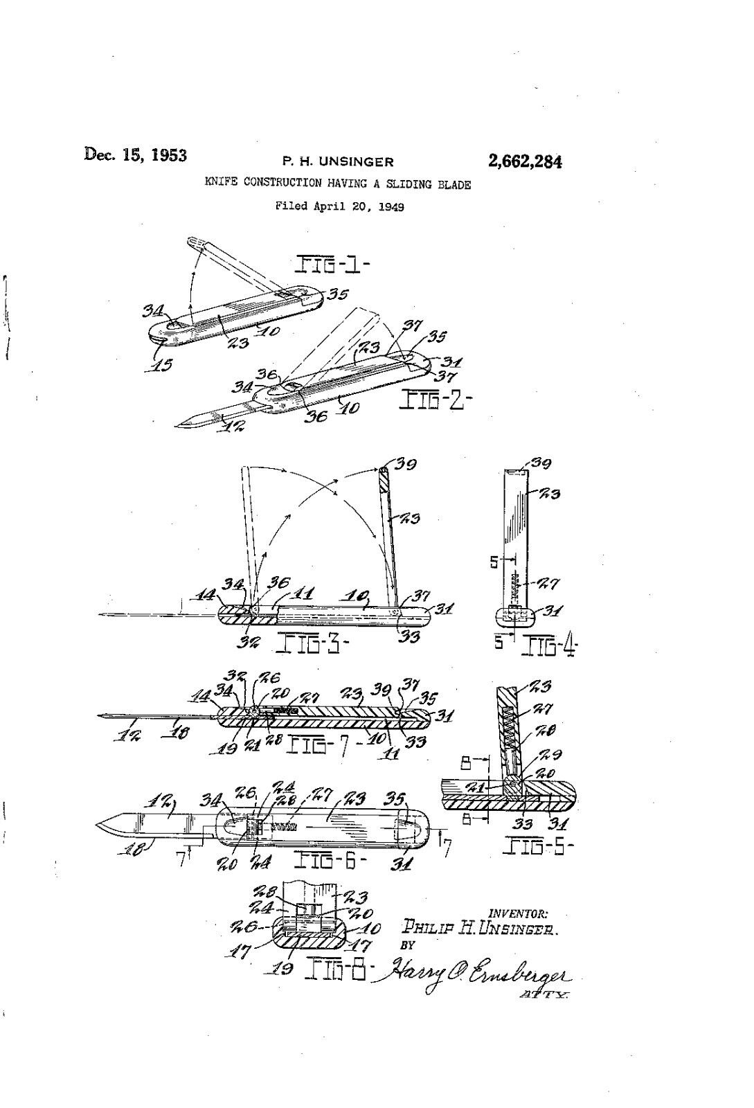
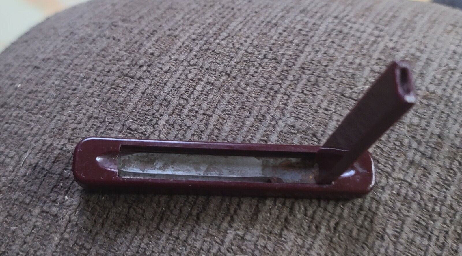
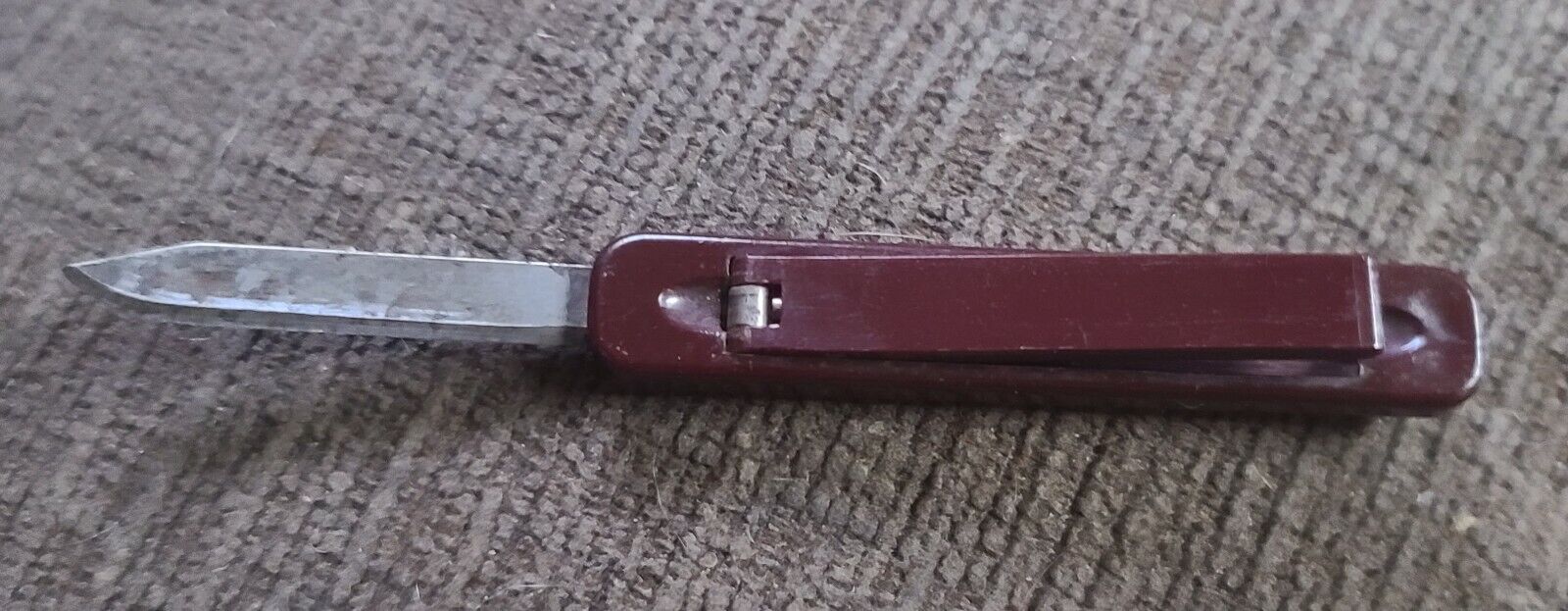
Made in 1949, made of Bake light material. Per internet info not sure. See pic and info below. Was called a construction Sliding knife blade first then later medical surgery knife. It is in good shape. Great for someone collection or collectibles.us patent search by number. US2662284A P.A. UNSINGER Inventor Philip H Unsinger Worldwide applications 1949US Application US88670A events 1949-04-20 Application filed by Russell Hicks 1949-04-20 Priority to US88670A 1953-12-15 Application granted 1953-12-15 Publication of US2662284A 1970-12-15 Anticipated expiration Status Expired - Lifetime Description Dec. l5, 1953 P. H. UNSINGER KNIFE CONSTRUCTION HAVING A SLIDING BLADE Filed April A20, 1949 Patented Dec. 15, 1953 KNlEE GONSTRUCTIQN llAVINCi e. sLImNG BLADE I hilip E. Unsinger, Fremont, Ohio, assigner, by mesne assignments, to Russell' Hicks, Lexington, Ky. nulication April 20, 194i!a Serial No- Sill! (Cl. atl-1:62) 4 Claims. This invention relates to knife construction and more especially to devices known as pocket knives, The present invention embraces the provision of a knife and handle construction wherein the knife blade is movable into and out of positionof-use with respect to the handle construction. An object of the invention resides in the provision of a knife blade and handle construction wherein the blade is slidably` retractable into the handle construction. Another object of the invention resides inthe use of a retractable blade knife wherein the blade is pivotallyconnected to a keeper member cooperating w-ith a handle portion for maintaining the blade in fully open or fully closed position. Another object of the invention resides in the formation of a handle construction preferably formed of plastic resin and which is provided interiorly with guiding ledges for the slidable blade, the ledges as a supporting and positioning means for the keeper. Another object of the invention resides in a handle construction for a slidable blade wherein the blade is held in either open or closed positien by a keeper, the keeper and handle construction being formed with interengaging configurations iormaintaining the keeper in a recess formed in the handle. Another object of the invention resides in the provision of a handle construction for a slidable blade knife which is molded of plastic resin and in which an end portion is cemented or bonded to the remaining portion of the handle after assemblv of the knife blade and keeper. Still another obiect of the invention is the provision of a knife construction of the slidable blade type wherein a keeper member is pivotally connected to the knife blade construction and resilient means are provided for establishing a friction factor between the keeper and the knife blade construction. Further objects and advantages are within the scope of this invention such as relate to the arrangement, operation and function of the related elements of the structure, to various details of construction and to combinations of parts, elements per se, and to economies of manufacture and numerous other features as will be apparent from a consideration of the specification and drawina of a form of the invention, whichmay be preferred, in which: Figure 1 is an isometric view illustrating the f knife construction of my invention with the knife blade retracted into the handley QllSlilllllDll ill an out-of-use position; Figure 2 is an isometric view showing the knife blade extended to a position-of-use; Figure 3 is an elevational View of the knife and handle construction, certain portions being broken away for purposes of illustration; Figure. 4 is an end View of the construction shown in Figure 3 with the keeper member illustrated in elevated or open position; Figure 5 isv an enlarged detail sectional view taken substantially on the line 5 -5 of Figure 4; Figure 6 is a plan view of the knife construction of my invention Showing the blade in extended position; Figure 'I' is a longitudinal sectional View taken substantially on. the .line 1-1 of Figure 6; Figure fi is a'. -fragmentary detail sectional view taken substantially on the lino 8-8 of .Figure While, I have shown a preferred form 01j the invention as embodied ln a pocket knife construetion. it is to be understood that I. contemplate the arrangement 01j my invention for other forms of knives and cutting instrumentalities.v Referring to the drawings in detaik the knife construction is inclusive of a handle Inomics? Il! which is Preferably formed of molded plastic resin but may, it ocsiurodl be manulacturofl. ol other materials. l have. found that o. plastic resin known as cellulose acetate loutvratc, may be used. for the handle construction, although any suitable. thermosettins or thcrmoscttablc resin, may be employed., The handle. l0 is provided with a longitudinally extending recess l! adopted to accommodate `a knife blade, l2 which is mounted for slidable movement in the rcocss.x Ons. end portion of the handle Illv is provided with, an enla/rood or brides portion I4, which with the body portion t0 provides a slot l5. through which the knife. blade lz may be projected 15o-open posi-N tion` As will be seen. in ligure 8. cach interior wall ol the handle il! adjacent the. olado l2 is formedw with a ledge portion. Il, one purpose, of which is to form longitudinal guiding moans for the slidable knife blade. l2.. The knife blade l2r is ol a flat type having a cutting edge i8 and. shank portion le, the latter being providcd'with an upwardly .or laterally extending member or projection 20. As illus: trated the projection 20 has a tenori portion 2| which is swagcd to secure the same to the shank of the knife blade although the projection may be. welded to the blade if desired. A kconcr member or bar 23 also ioriocd or molded of plos= tlc resin or the like is provided, one, cud bolus provided with turcatious 24. which stradale the projection 2n carried by the shank portion o! the knife blade. "The'iurcations and projection 20 are formed with aligned openings to receive a pivot pin 26 whereby the keeper 23 is pivotally connected to the knife blade. The keeper 23 is formed with a longitudinal bore in which is retained an expansive coil spring 21 and a plunger or pin 28, the latter, under the influence of the spring, being urged into frictional engagement with the arcuate upper surface 29 of projection 2). The plunger 28 engaging the projection 20 provides a frictional force so that the keeper will be frictionally retained in any relative position with respect to the blade l2. The opposite end of the handle I is adapted to receive a portion 3| which functions as a closure for the recess formed in the handle and maintains the blade and keeper in assembled relation with the handle. The member 3| may be cemented or bonded to the handle portion after assembly of the knife blade and keeper construction. The portion I4 of the handle I0 and the member 3| are of similar configuration in those portions engageable with the keeper or bar 23. As particularly shown in Figures 3. 5 and '7, the portion |4 and member 3| are formed with canted surfaces 32 and 33. The portion |4 and member 3| are also provided with shallow recesses 36 and 35 to accommodate the fingernail of the knife user for manipulating the keeper bar 23. The canted surfaces 32 and 33 at their point of intersection with the upper surfaces of the handle form keeper retaining edges 3S and 31. The outer end of the keeper is provided with a transverse recess or kerf 39 to accommodate the ngernail of the knife user so that the keeper may be swung upwardly as shown in broken lines in Figures 1 and 2. This is accomplished by the user inserting a fingernail in one of the recesses 34 or 35 depending upon the particular closed position of the keeper 23 and by upward force of the fingernail the keeper 23 will be forced past the locking edges 36 or 31. In assembling the knife construction, the blade l2 is inserted in the open recess prior to assembly of member 3| with the handle |0. After the knife blade |2 has been inserted in the In the use of the knife, assuming that the blade is in an out-of-use position as shown in Figure l, the user desiring to open the` knife places a fingernail in recess 34 in the handle I0, the fingernail projecting into recess 39 of the keeper bar 23. The user then exerts an upward force to disengage the end of the keeper from the canted surface 32 and locking edges 36 swinging thekeeper to the position shown in full lines in Figure 3. With the keeper in a vertical or elevated position the user moves thekeeper body in a lefthand direction asviewed in Figure 3 so that the keeper occupies the position shown in dotted lines in Figure 3. The keeper is then pivoted about the pin 26 into the recess I in the handle to the position shown in Figure '7. As securely held in open position by. interlocking,v engagement of thel end of the keeper 23 with j member 3 When itis desired t0 Close the knife or move the blade to an out-of-use or retracted position, the user places a fingernail in recess 35 in member 3| with the end of the nail projecting into the transverse kerf or groove 39 in the keeper. The user exerts an upward force upon the keeper and the reverse movements of the keeper and blade are effected to slide the blade into the recess in the handle I0. After the blade is moved to completely closed position the keeper 23 is swung into the recess to occupy in the knife handle as shown in Figure l. The keeper in this position is latched in closed position by the edges 36 so as to prevent inadvertent movement of the knife blade toward open position. It is apparent that, within the scope of the invention, modifications and different arrangements may be made other than is herein disclosed, and the present disclosure is illustrative merely, the invention comprehending all variations thereof. What I claim is: l. A knife construction comprising a molded plastic handle, said handle having a slot therein opening at one end of said handle, a knife blade disposed in said slot and slideable therein, said handle having a recess in a side meeting and opening into said slot and wider than said slot so as to form shoulders with said slot, a keeper pivotally connected to said knife blade at the shank end and adapted to be bottomed against said shoulders and fitting into said recess when the blade is in open or closed position, said keeper having its free end beveled, and inwardly canted surfaces at the ends of said recess for engagement with the beveled end of said keeper to lock said keeper when the blade is in the open or closed position. 2. A knife construction comprising a molded plastic handle, said handle having a slot therein opening at one end of said handle, a knife blade disposed in said slot and slideable therein, said handle having a recess in a side meeting and opening into said slot and wider than said slot so as to form shoulders with said slot, a keeper, a pivot connecting said keeper to said knife blade at the shank end of said blade, said keeper adapted to be bottomed against said shoulders and fitting into said recess when the blade is in open or closed position, said keeper having its free end beveled, inwardly canted surfaces at the ends of said recess for engagement with the beveled end of said keeper to lock said keeper when the blade is in the open or closed position, and resiliently biased means carried by said keeper and acting against said pivot for setting up a component of friction between said keeper and said projection. 3. A knife construction composing a molded plastic handle formed from two pieces of molded plastic fused together, said handle having a slot therein opening at one end of said handle, a knife blade disposed in said slot and slideable therein, said handle having a recess in a side "meeting and opening into said slot and wider than said slot so as to form shoulders with said slot, a keeper pivotally connected to said knife blade at the shank end and adapted to be bottomed against said shoulders and fitting into said recess4 when the blade is in open or closed position, said keeper having its free end beveled, and inwardly canted4 surfaces at the ends of said recess for engagement with the beveled end of said keeper to lock said keeper When the blade is in the open or closed position. f 4. A knife construction comprising a molded plastic handle, said handle having a slot therein opening at one end of said handle, a knife blade disposed in said slot and slideable therein, said handle having a recess in a side meeting and .j opening into said slot and Wider than said slot so as to form shoulders with said slot, a keeper pivotally connected to said knife blade at the shank end and adapted to be bottomed against said shoulders and tting into said recess when the blade is in open or closed position, said keeper having its free end beveled, inwardly canted surfaces at the ends of said recess for engagement with the beveled end of said keeper to lock said keeper when the blade is in the open or closed 15 position, said keeper having its free end recessed, and iingernail grooves in said handle at either end of said handle recess to allow for disengaging the keeper from the locked position. PHILIP H. UNSINGER. References cited in he me of this patent UNITED STATES PATENTS Number r 242,985 530,913 576,862 1,546,709 1,639,441 2,252,896 Number Name Date Rischow June 14, 1881 Cook Dec. 11, 1894 Lebold Feb. 9, 1897 Batt July 21, 1925 Spahr Aug. 16, 1927 Mounts Aug. 19, 1941 Mirando Aug. 23, 1949 FOREIGN PATENTS Country Date Italy June 24, 1935 France June 21, 1923
